
Hello friends foes and other assorted digital miscreants
I am continuing to work on the writer deck project. The keyboard is done for now, but will surely be revised before production.
In the meantime, let's take a look at what I learned, accomplished, and failed-at in designing the mainboard
PCI Express
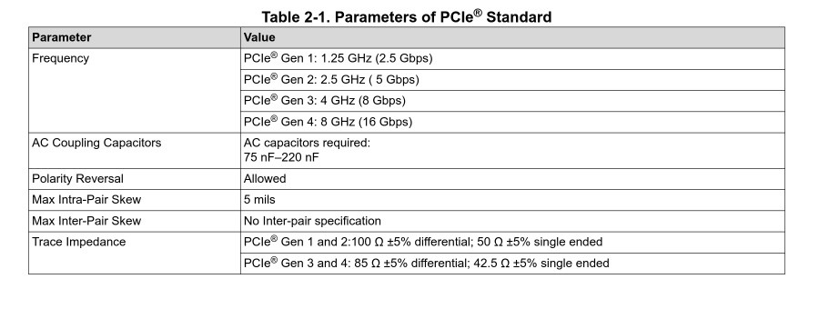
PCIe (Peripheral Component Interconnect Express according to Wikipedia) is, put simply, a serial bus. It's based on "lanes", which are pairs of buses, each of which is comprised of a differential pair (think D+ and D- in USB 2, or more accurately TX+/- and RX+/- in USB 3). Now, we all knew this already. What I didn't know, and it took me a while to figure out is our old friend: the differential impedance of the pair on the board, since to be compliant with the PCIe standard we need to have a Zdiff of about 100ohm [1], to be impedance matched. It is allowed, from what I've seen, to stray a tiny little bit, and especially it's not required for vias (the little holes in a PCB that carry the signal from one copper layer to another) to be impedance matched, and thank the gods for that, as otherwise this headache of mine would have gotten even worse.
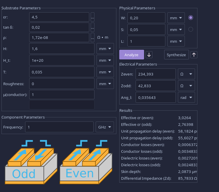
But, back to the practical side of things: this is trivial right? we put our board manufacturer's minimum parameters into the KiCad calculator tool and aim for a Zodd of about 50ohm (as Zodd = Zdiff/2), easy peasy, right? nothing we haven't done a thousand times, RIGHT?
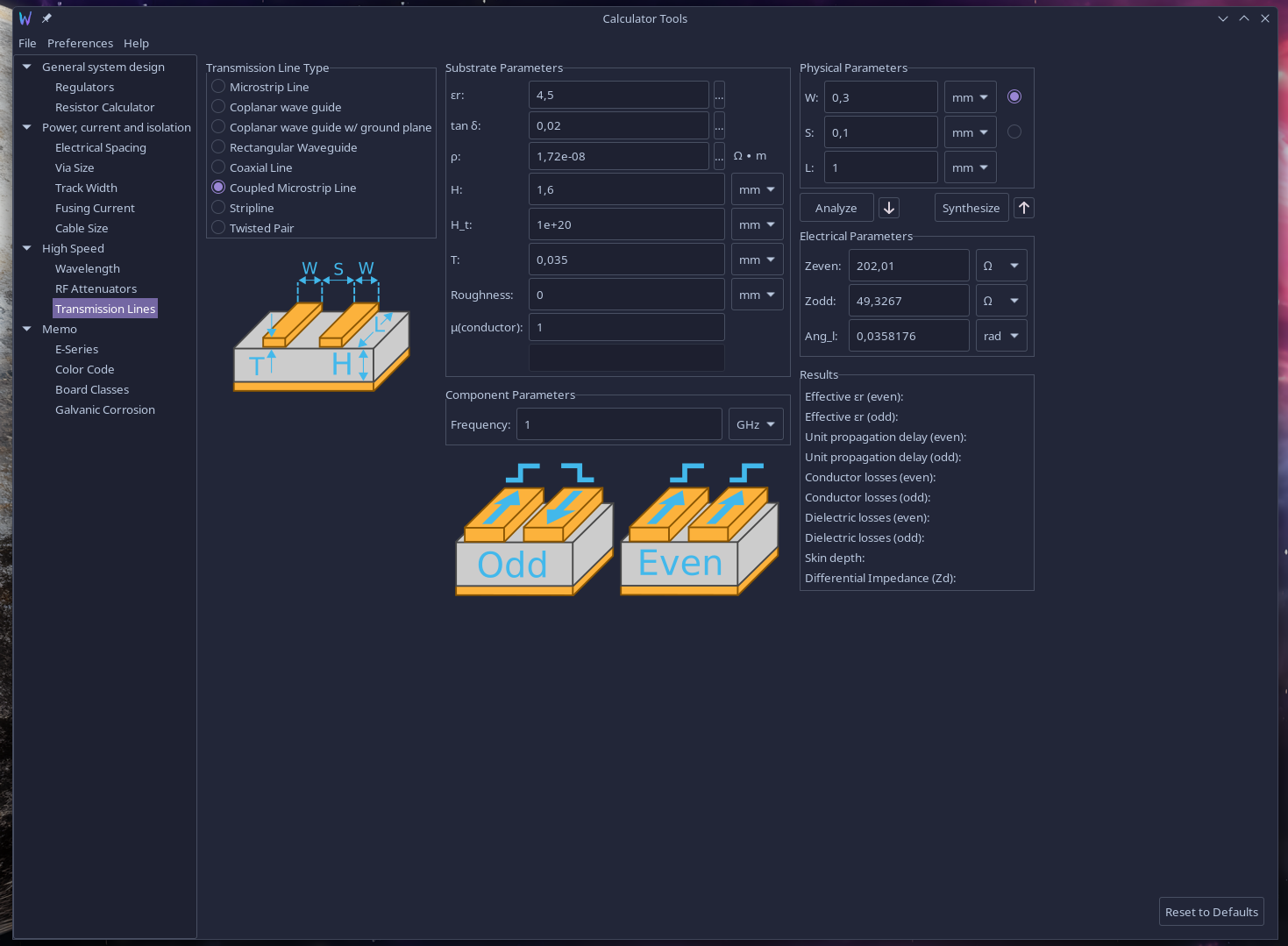
Oh no mes amis, we screwed up big time here. You see, the 100ohm differential impedance is up to PCIe 2. PCIe 3 and 4 require a 85ohm one as specified by this helpful table [2] (on a side note, dear Texas Instruments, I swear your design guidelines documentations are giving me a crash course in electronic engineering that I will forever be grateful for. The series on pcb capacitive touch sensors is so well written I thought I had accidentally purchased a book)
Aaand oops, 85ohm. No biggie, let's fiddle around with the calculator until we get a Zodd of ~42.5ohm and we're good to go
Okay, so, our pins are very, very close together
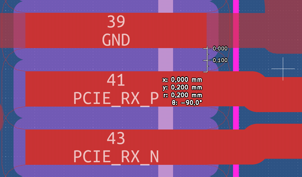
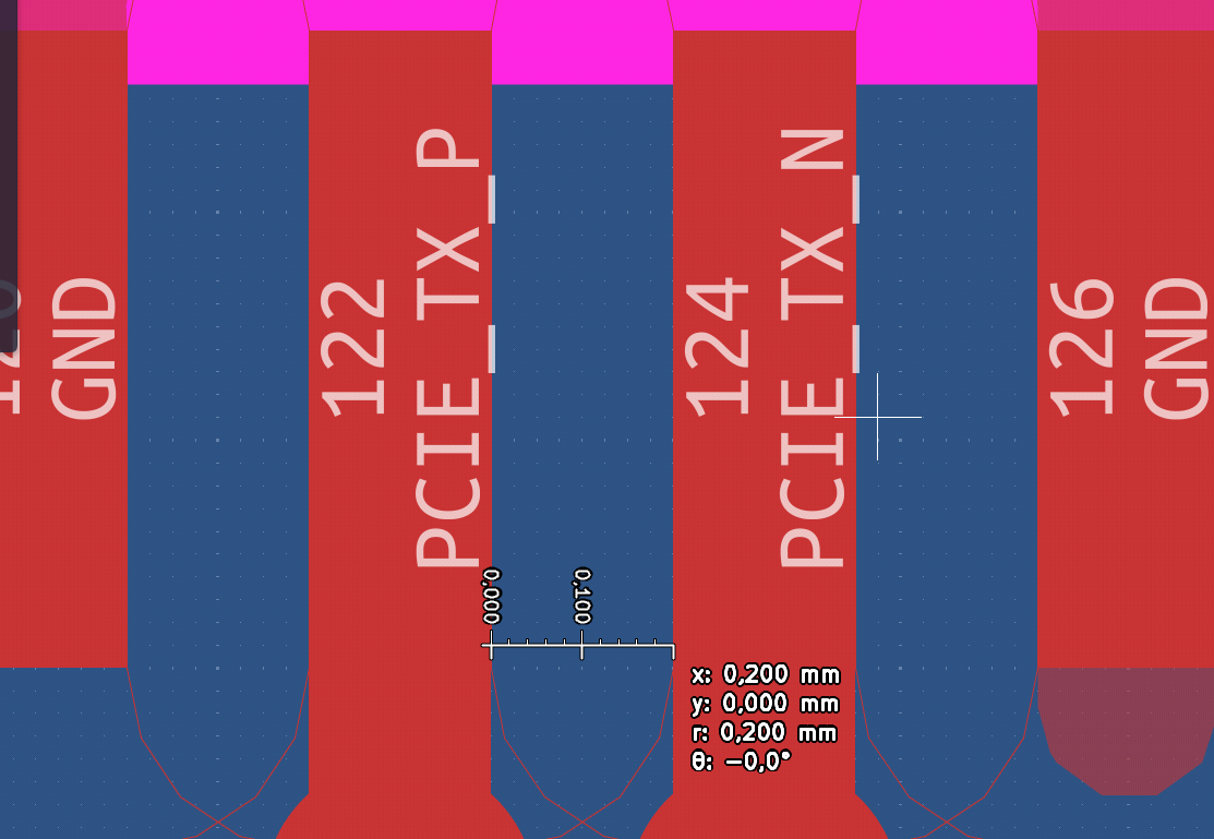
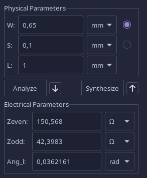
Just fan out, I hear you say, and yea sure I could, but I am not a big fan of the insane impedance jump between connector and trace. Now, a better and more experienced engineer than me would go for a 4 or 6 layer board, in order to stack the traces vertically, having them much much closer, because as we see here
Halving the distance between the lines way-more-than-halves the required trace size. And our chosen board manufacturer very easily allows us to have layers that are separated by 0.5mm or less (JLCPCB please sponsor me I'll be good I swear). And a multilayer board would allow us to sandwich our differential pairs between ground planes, that would greatly help signal integrity and interference/parasitics management.
Or I could cheat instead, you see, the RPi CM5 upon which we're building this whole design does have a single lane of PCIe, and it's recommended to use it at 2.0 speeds, not 3.0. Furthermore, the 2.0 speeds are still very very acceptable, with a 500MB/s throughput per lane in full-duplex mode. They are so acceptable that my gaming pc hardly saturates 16x of them, and I play in 2k at "high" graphics presets with an RTX2060 super (which is also a randomly blessed golden silicon but that's irrelevant here, I just really like my gpu)
Thus, what do: more expensive and fancier pcb that can handle gen3 and gen4 speeds, or a more affordable one that can only go up to gen2? Hopefully I will reach a decision and let you know in the next update
USB-C, Power Delivery
Those who know me know that I really like USB-C: It's an objectively well-designed connector, which when paired with >3.0 standards, alt-mode, and PD protocol allows for a very unified experience. Those who know me well also know that I really dislike the fragmentation in the cables and power supplies market. I have drawers full of USB-C cables that do not have the CC wires (indispensable for negotiation of PD parameters), I have at least 3 "docking station" thingies that do not in any way break out the i2c lines from HDMI, and thus do not allow me to change brightness and other parameters of connected monitors from ddc. I even asked a big company that manufactures docks and they don't make any that is ddc compliant so yay.
But, back to the task at hand, I want a USB type C connector to charge the device. It has to be USB-C PD compatible. Data is honestly optional at this point but ideally the ports would be as follows:
- 1x USB-C for charging with 5Gbps data
- 2x USB-A with 5Gbps data
- 1x HDMI
- 1x RJ45 Ethernet is I feel fancy
Thing is, the RPi CM5 only has support for 2 USB3.0 ports, and 1 USB 2.0 "Use a hub" I hear you say, and you're right. Hub controllers aren't trivial to implement tho and this is secundary to the big big problem I'm having
PMICs and BMSs are hard
I talked about wanting the device to be battery-powered, somewhat obviously since it's supposed to be a portable computer. The problem lies in the absurd vastity of PMIC (Power Management Integrated Circuit) and BMS solutions available, how hard it seems to be to find any that fit my specs, and the fact I'm lowkey healthily terrified of batteries. This is stumping me, also because I'm not yet totally sure what kind of battery capacity and technology to play with here: should I use a widely available cell phone battery like the S23 Ultra at 5Ah? or a bunch of custom-packaged 18650s? And should I aim for 7.4V to be stepped down, or should I try to boost some 3.7V up? (no okay I hear it, I'mma go step-down way)
So yea, hope y'all enjoyed reading up on my struggles. I hope I will update you soon, but in the meantime this should act as somewhat of a cross between a todo list and a checkpoint
Have a wonderful day :3
-Aki